Prototyping: Ideate & Iterate
One of our team's strengths was that we prototyped early and we prototyped a lot. We mocked up many different shooting mechanisms, tested dozens of alterations on our beacon detection circuit, and went through four builds (not even counting the Lego version you see above). The four build phases are listed below, and after every description are the major design issues we learned when designing/assembling/running for that respective prototype.
Shoot, Layup, or Dunk??
Early scissor lift concept with dumper
Form follows function, so the first and most basic decision that had to be made was how the robot was going to score points. Shooting the ball from far away would have to have an incredibly repeatable shooting mechanism, and extremely accurate alignment with the hoop. The idea did not seem very attractive at first given these constraints.
Our initial prototypes centered around ways to directly dump a bunch of balls into the hoop at once, but Mechanical complexity and fears over a possible disqualification if we touched the hoop made these less attractive. The centrifugal wheel shooters that seemed popular just seemed too hard to construct and control to be believably feasible. Without any better ideas, It looked like a "dumper" robot and a LOT of time in the PRL was going to be the best option...
Our initial prototypes centered around ways to directly dump a bunch of balls into the hoop at once, but Mechanical complexity and fears over a possible disqualification if we touched the hoop made these less attractive. The centrifugal wheel shooters that seemed popular just seemed too hard to construct and control to be believably feasible. Without any better ideas, It looked like a "dumper" robot and a LOT of time in the PRL was going to be the best option...
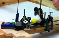
Initial shooter prototype (ruler cocked)
Then with a stroke of good luck, an idea for a really simple linear spring based shooting mechanism came up. We thought it might be appropriate for a close "Lay up" sort of shot. We built a simple prototype out a stainless steel ruler, some wood, legos and a bunch of clamps. The results were astoundingly repeatable. We were able to shoot a full 3.5 feet, and put every landing within a 2 inch diameter. Plus the mechanism we came up with was very simple! This was clearly the basis for good shooting, and if it could be combined with an accurate beacon alignment, could possibly make long distance shooting actually feasible.
Build Phase I
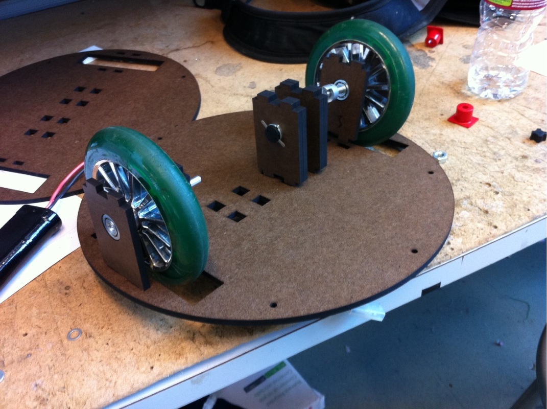
The first drive base prototype
Two separate modules were built: (1) a drive base made from lasercut masonite and (2) a prototype out of Legos and wood. The intention was to get a driving base to test beacon detection, while at the same time get a jump start on testing reliable shooting mechanisms. We spent a significant amount of time in the machine shop to make a motor-couping-to-wheel adapter out of aluminum (our only machining during the project) because we knew that this would be the only part that would be kept throughout all the build phases.
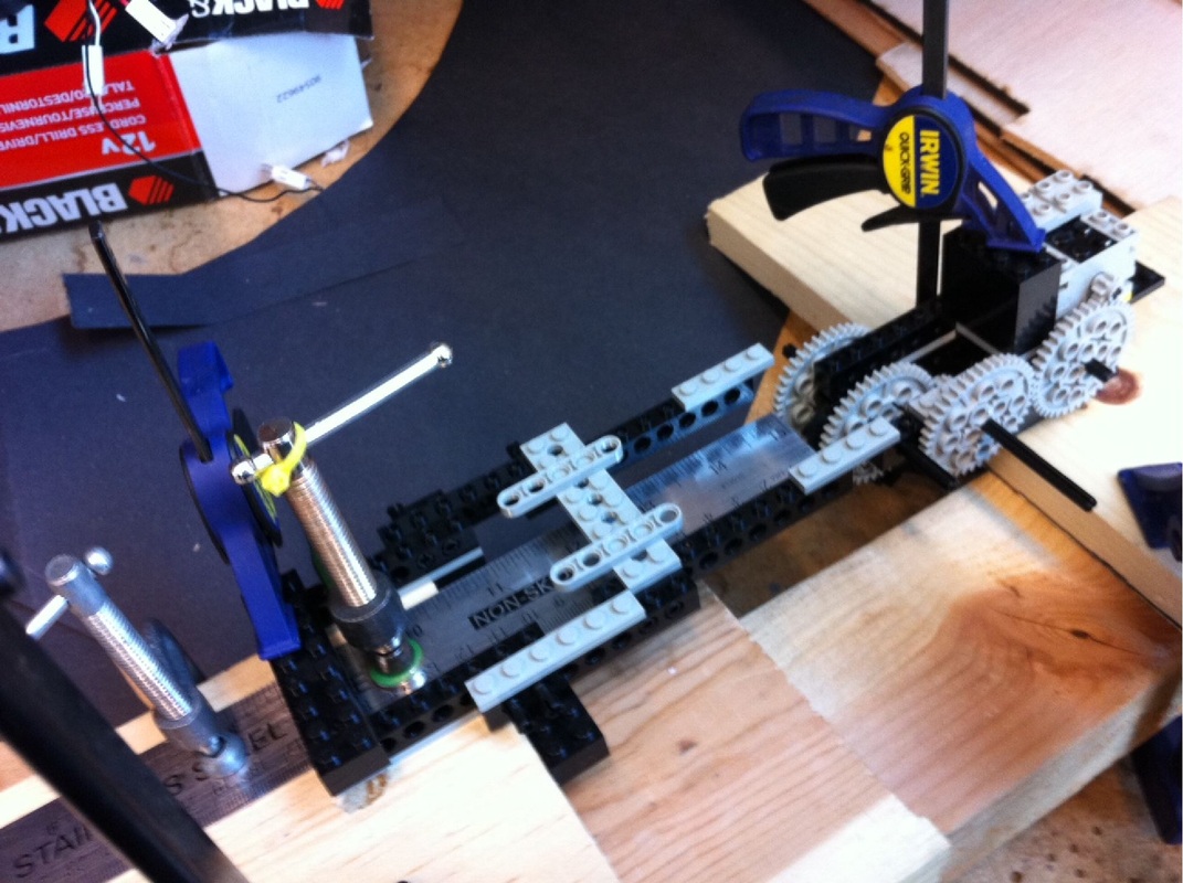
Shooter prototype from Legos and wood
The Lego-wood shooter was arguably more accurate than our final build (which could make 80 to 90 percent of shots). We fell victim to the whole school of thought that Legos are for prototyping and not final products, when in fact their injection molded plastic is some of the best out there (lego block wins vs. servo horn in a rigidity contest any day).
Major design issues uncovered:
Major design issues uncovered:
- Make motor and bearing blocks shorter because of height limitations
- Top tabs of motor and bearing blocks should only have one tab, and not two. This reduced the difficulty of assembly and eliminated the possibility of inserting a bearing block up-side-down.
Build Phase II
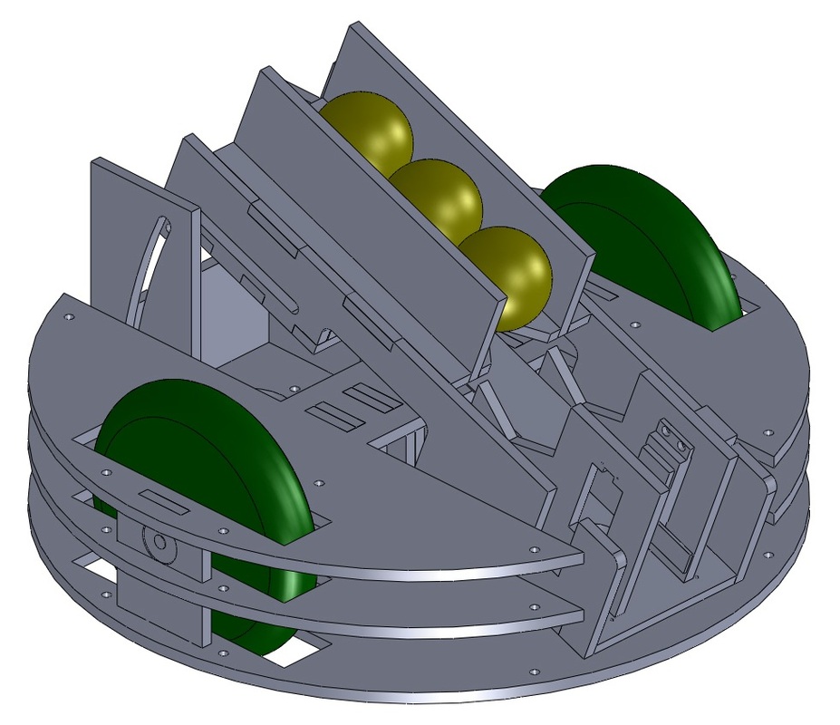
CAD drawing of Prototype 2
This build was aimed at integrating the shooter onto the robot base. We made two large cut-outs from the top plate to sit the shooter platform on the bottom plate. The shooter was hinged at the front of the robot and had a full range of motion from 5 to 30 degrees (to test out different shooting strategies), getting support from two towers that extended from the base at the back of the robot. This build had a chute that sat parallel to the ruler mechanism and loaded the shooter (no ball gate was made at that time) from above. The chute was removable and just sat in tabs, as it only took the little load from the weight of balls. We planned on prototyping a funnel that guide balls to the top of the chute.
Major design issues uncovered:
Major design issues uncovered:
- There was no way we could feed the balls from above into the shooter. We needed space for our beacon sensing turret. Any chute/funnel we made would have to feed the shooter from the side
- There was no need to adjust the shooter from 5 to 30 degrees. Our shooter found a sweet spot at approximately 25 degrees, so the next build only had to support angles of 20 to 30 degrees.
Build Phase III
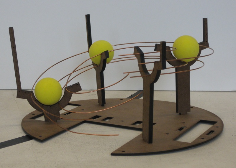
Ball harvester for build phase 3
The third build was focused on prototyping the chute/funnel and the beacon sensing turret. The "ball harvester" was made using 1/16" welding rod (steel core with copper coating), and it could feed directly into the side of the shooter by making a partial "helix" around the robot. Four posts of varying heights were set up in a circle around the robot and wires fed through them. At this point in the project both LaserCAM machines in the PRL were actually down, so we could only cut the parts out of 1/8" masonite. This made the ball harvester less sturdy, but at the same time we learned that we could make the beacon sensing turret out of the thin material, decreasing our total robot height, which was a huge plus. We ended up retaining the turret as part of our final design (build 4).
Major design issues uncovered:
Major design issues uncovered:
- 20 degree field of view is a bit too large for the IR transistors; there is a significant drop off in sensitivity right at 20 degrees.
- Steel wires are hard to bend in an arc
- Need to design the harvester supports so they arc into the shooter. This would make wire bending significantly easier.
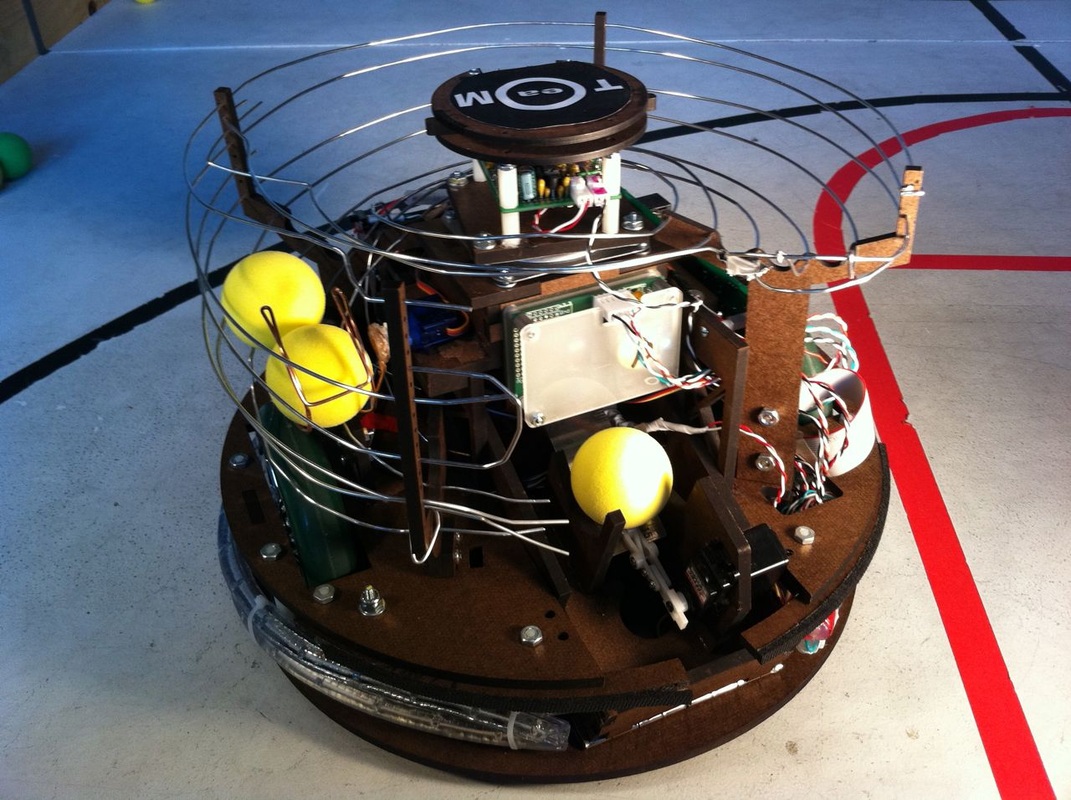
Build Phase IV
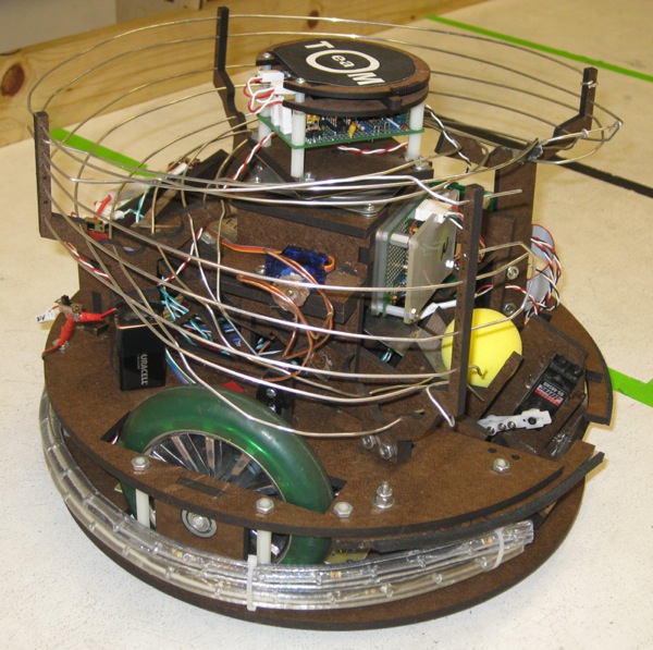
Finished competition robot
This build took into account all of the design issues that were raised in the previous builds. We limited the shooter adjustment angle between 15 to 30 degrees, and by doing so we were able to put its support towers on the top platform, freeing up space on the bottom platform for batteries and circuit boards. The support towers were extended to add space for the turret assembly to sit. The viewing angle of the IR transistors were decreased to 15 degrees. We were also able to get 1/16" aluminum wire for the harvester which made the wire bending significantly easier.
Some new additions to this build were the ball gate (and the servo it attaches to) and tape sensor to detect balls at the gate. These were done in-situ because we did not have a full model of the harvester (wire routing is impractical to do in SolidWorks) so we would not know exactly where to put these components. We also had time to add aesthetic lighting to our robot as well!
Some new additions to this build were the ball gate (and the servo it attaches to) and tape sensor to detect balls at the gate. These were done in-situ because we did not have a full model of the harvester (wire routing is impractical to do in SolidWorks) so we would not know exactly where to put these components. We also had time to add aesthetic lighting to our robot as well!
